
How Oscillating Fans Work

Table of Contents
On a hot day, a bit of moving air can greatly improve the atmosphere of any environment. If an air conditioner is out, a fan is a welcome appliance.

Inroduction to the Oscillating Fan
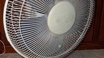
More air can be distributed to a larger crowd if the fan happens to be an oscillating fan--meaning that it turns from side to side, changing the direction of its air current. The fan can switch easily between a standard mode and oscillation with the push of a knob.
Design Basics
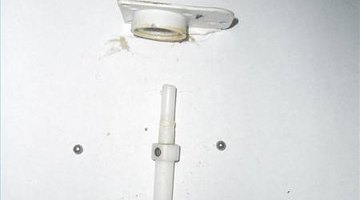
From the ground up, the fan consists of a base, controls, motor, propeller and, in this case, gears. The fan head, which includes the motor gears and propeller, must be on a joint to allow the whole head to pivot. A dual pivot device is required, one pivot for the head and the other for the lever to turn the whole assembly.
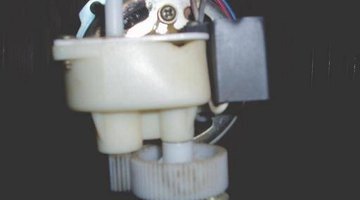
Motor
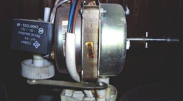
The head contains all of the workings in the fan. The motor's rotating rod sticks out both ends, with the propeller directly attached to one end of the rod. On the other end of the rod is a gearbox which controls the oscillation. The end of the motor rod that enters the gearbox is threaded, which then makes contact with a gear. This gearbox allows the fan to oscillate without using a separate motor, making for an efficient design.
Knob Insert Design
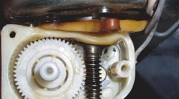
The core of this gear is enlarged, and allows for an insert to slide up and down in it. The insert has a hole through it that houses a spring with ball bearings on either side. When the ball bearings are pushed outward, they behave like a gear when pressed against the core of the larger gear. This is used to prevent the fan from rotating against resistance, which may damage the fan or injure someone.
Insert Function
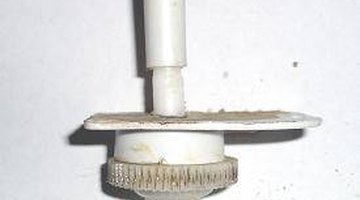
The roof of the gearbox has a similarly shaped core, and when the insert is moved upward, the ball bearing position is moved into the core area of the gearbox roof, which is stationary. This accounts for the static mode of an oscillating fan. The insert has a knob that extends to the outside of the fan casing, which allows the operator to switch between these two modes. The operator will notice that the knob will slowly rotate when it has been pressed down, but not when it is up.
Lever Gear
The bottom end of the insert is a gear. This gear is always touching a gear that is located on the underside of the gearbox. This gear has a lever attached to one side of its face. The other end of the lever is attached to the frame. This design changes the rotation motion of the gear into the side-to-side sweeping motion that makes the oscillating fan.
The Drip Cap
- On a hot day, a bit of moving air can greatly improve the atmosphere of any environment.
- The fan head, which includes the motor gears and propeller, must be on a joint to allow the whole head to pivot.
- The head contains all of the workings in the fan.
- This accounts for the static mode of an oscillating fan.
- The other end of the lever is attached to the frame.
- This design changes the rotation motion of the gear into the side-to-side sweeping motion that makes the oscillating fan.
Writer Bio
Cade Bartlett is a college student in Arizona. Although his Computer Science and Engineering major doesn't account writing, he has always excelled in english courses, as well as most other areas. He enjoys working with computers and occasionally exercising his artistic abilities in many ways.
More Articles