
How to Wire a Shed for Electricity

Spring is here and many homeowners are thinking about building storage sheds to store their yard and garden equipment. Many of the more knowledgeable do-it-yourselfer will build their shed from scratch while less knowledgeable DIYers will buy a prefabricated shed and assemble it on site.
The one thing that even prefabricated shed kits lack is the wiring for a light and a receptacle or two. Wiring a small storage shed isn't a major electrical project but you will need to "pull" a permit and have all the required electrical inspections performed by the Authority Having Jurisdiction (AHJ.)
Things You Will Need
- Wiring permit
- Layout stakes
- Mason's cord
- Sledgehammer
- Trenching shovel
- 1/2-inch hammer drill
- Hole saw attachment
- 1 and 1/4-inch PVC schedule 40 electrical conduit
- 21/2 w/Gr. Type UF cable
- cable cutters
- Spade bits
- Hammer
- Cable staples
- 4-inch square junction box
- 5 "New Work" device boxes, metal
- 1 "New Work" lighting outlet box, metal
- 12/2 w/Gr. ROMEX® cable
- Diagonal pliers/wire cutters
- Wire strippers
- Lineman's pliers/Electrician's pliers
- Wire nuts
- Needle nose pliers
- Electrician's screwdrivers
- 4 duplex receptacles
- 1 light switch
- One 4-foot, 2-tube, fluorescent shop light fixture
- One 20-Ampere, 120-Volt, GFCI Circuit Breaker
- Electrical spray foam sealant
- Rough-in inspection
- Blank junction box cover
- 4 flush, metal duplex receptacle covers
- 1 flush metal switch cover
- Final inspection
-
Purchase an electrical wiring permit from the AHJ. Don't start this project until you have the wiring permit and have it posted in plain sight on the shed.
-
Layout the route that the underground feeder (UF) cable will take from the main service circuit breaker panel to the shed. Drive the layout stakes in the ground with the sledgehammer and join them together with the Mason's cord. This will keep your trench straight. Dig the trench at least 24-inches deep per Table 300-5 of the National Electrical Code (NEC.)
-
Drill 1 1/4-inch holes where the cable will enter the shed and where it enters the house. Sleeve these holes with lengths of 1-inch PVC conduits to protect the cable from damage. This is required by the NEC. Once the cable is in place, you will seal these lengths of conduit with spray foam to prevent the entrance of moisture into the buildings.
-
Route the Type UF cable from the house to the shed. On the house end cut the cable long enough to reach the main service panel. Route the cable along the side of floor joists or perpendicular to the floor joist by passing it through drilled holes. Drill 3/4-inch holes so that the near edge of the holes is at least 1 1/4 inches from the nearest edge of the floor joist. Don't install the cable in the service panel yet.
-
On the shed end of the cable, secure the 4-inch square junction box as close to the point of entry as possible. Insert the UF cable into the junction box at least 6-inches per NEC requirements. Mount the receptacle devices evenly around the shed. For a 12 foot-by-14 foot shed mount the first one 6 feet from the door and the remaining receptacles at 12 foot intervals. Since this is a shed, mount them at a height of 48 inches above the floor.
-
Mount the device box for the light switch 48 inches above the floor opposite the hinged side of the door. Mount the lighting outlet box as near the center of the ceiling as possible.
-
Route lengths of 12/2 w/Gr. ROMEX® from the junction box to the first receptacle device box. Route sections of ROMEX® between each of the receptacle device boxes. Insert the cable ends at least 6 inches into the boxes.
-
Route lengths of ROMEX® from the junction box to the switch device box and form the switch to the lighting outlet box.
-
In all the boxes, remove the cable's outer jacket using the razor knife being careful to not damage the insulation on the individual wires. Remove 1 inch of insulation with the wire strippers from the ends of the insulated conductors.
-
Make up all the splices in the junction box. Hold the stripped ends of all the black wires side by side and twist them tightly together in a clockwise direction using Lineman's pliers. After twisting the wires together, screw on a wire nut. Inspect to be sure that no bare copper is showing outside of the wire nut. If necessary, remove the wire nut and trim back the twist until no bare copper shows outside of the wire nut. Repeat for the white wire.
-
Splice the bare copper grounding wire together with a 6-inch bare copper pigtail. Bond; connect, the spliced grounding wires to the metal box with the free end of the pigtail. Make a loop in the end of the pigtail with the needle nose pliers and place it in a clockwise direction under the box's green grounding screw. Don't cover this box until after the rough-in inspection.
-
Make loops in the ends of all the other stripped insulated wires for the receptacles and switch. In all the device boxes make two pigtail splices with the bare grounding wires and connect one of the pigtails to the boxes grounding screws.
-
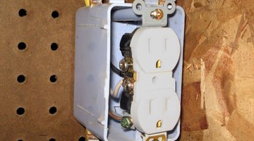
Connect each of the receptacles as follows. Connect the black wires to the brass screws, the white wires to the silver screws and the bare grounding pigtails to the green grounding screws. Don't install the receptacles in the boxes until after the rough in inspection.
-
Connect both black wires in the switch box to the brass screws on the switch. Splice the two white wires together and connect the bare grounding wires to the box and to the switch just as you did for the receptacles. Leave the switch hang by the wires until after the first inspection.
-
Turn off the main breaker and remove the cover to the service panel. Install the GFCI breaker. Depending on your panel, this breaker may simply snap in place or it may be secured to the Buss Bars by a screw. Uncoil the breaker's white pigtail lead and secured the stripped end under a compression screw on the panel's neutral bar.
-
Install the cable in the panel. Connect the black circuit wire to the brass screw on the breaker and connect the white circuit wire to the silver screw on the breaker. Connect the bare copper grounding wire to the panel's grounding bar. With the new breaker in the off position, turn on the main breaker. Don't close up the panel.
-
Call for the rough-in inspection.
-
Install the receptacles and switch in the boxes. Install the cover plates. Install the lighting fixture by securing it to the box and splicing the white, black and grounding wires together. Call for the final inspection.
The Drip Cap
- Spring is here and many homeowners are thinking about building storage sheds to store their yard and garden equipment.
- Many of the more knowledgeable do-it-yourselfer will build their shed from scratch while less knowledgeable DIYers will buy a prefabricated shed and assemble it on site.
- Route the cable along the side of floor joists or perpendicular to the floor joist by passing it through drilled holes.
- Mount the device box for the light switch 48 inches above the floor opposite the hinged side of the door.
- Route lengths of 12/2 w/Gr.
- Route sections of ROMEX® between each of the receptacle device boxes.
- Insert the cable ends at least 6 inches into the boxes.
- In all the boxes, remove the cable's outer jacket using the razor knife being careful to not damage the insulation on the individual wires.
- Don't cover this box until after the rough-in inspection.
- Connect each of the receptacles as follows.
- Connect the bare copper grounding wire to the panel's grounding bar.
- Call for the rough-in inspection.
- Install the receptacles and switch in the boxes.
References
- cornerhardware:Installing a GFCI
- "National Electrical Code"; NFPA; 2008 Revision
Writer Bio
Based in Colorado Springs, Colo., Jerry Walch has been writing articles for the DIY market since 1974. His work has appeared in “Family Handyman” magazine, “Popular Science,” "Popular Mechanics," “Handy” and other publications. Walch spent 40 years working in the electrical trades and holds an Associate of Applied Science in applied electrical engineering technology from Alvin Junior College.
Photo Credits
- electric outlet image by Dawn Williams from Fotolia.com
- electric outlet image by Dawn Williams from Fotolia.com
More Articles