
How to Wire a Compressor, Fan Motor & Capacitor

The compressor, fan motor and capacitor work together in an air-conditioning system's condensing unit. The wires feeding high-voltage electricity to the condensing unit connect to a contactor's line-voltage terminal and the air-conditioning system's low-voltage signal wires connect to the contactor's coil.
When the low-voltage signal activates the contactor's coil, the contact points close and the high-voltage electricity energizes the compressor, fan motor and capacitor. The compressor and fan motor use the capacitor to maintain a constant running speed.
Wire Your Unit
-
Set the thermostat's function switch to the "Off" position and turn off the condensing unit's circuit breaker.
-
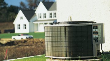
Remove the condenser's electrical service box cover with the correct screwdriver, usually a quarter-inch or five-sixteenths-inch hex screwdriver. The wires from the house enter the bottom of the service box. An air conditioner's electrical service box contains a contactor and the capacitor.
-
Examine and understand the condensing unit's wiring diagram, usually located on the inside of the service box's cover. The wiring diagram identifies the fan motor and compressor's wire colors and functions. A wiring chart on the fan motor's case also identifies the fan motor's wire colors and each wire's function. The letters stamped into the compressor's housing near the wire terminals identify each terminal function.
-
Examine the top of the capacitor. The labels next to each terminal identify the capacitor terminal's function.
-
Run the fan motor and compressor's wires to the electrical service box.
-
Push the wire connector on the fan motor's wire with the "Capacitor" or "Cap" function onto the capacitor's terminal with the "Fan" label. Usually the fan motor uses brown insulation on its capacitor wire.
-
Press the wire connector on the compressor's wire with the "Start" or "S" function onto the capacitor's "Herm" terminal.
-
Press the wire connector on the short wire from the contactor's "L1" terminal onto the capacitor's "Common" or "Com" terminal. The white wire from the circuit breaker often connects to the input side of the contactor's "L1" terminal.
-
Insert the end of the compressor's wire with the "Run" or "R" function into the contactor's "L1" terminal. If the wire uses a wire connector, press the connector onto one of the contactor's "L1" prongs. If the wire does not use a connector, slide the end of the wire into the screw-operated terminal and tighten the screw with a Phillips screwdriver.
-
Push the wire connector on the fan motor's "Common" wire onto one of the contactor's "L1" prongs.
-
Connect the compressor's wire with the "Common" or "C" function to the contactor's "L2" terminal. The black wire from the circuit breaker usually connects to the input side of the contactor's "L2" terminal.
-
Slip the wire connector on the fan motor's wire with the "Hot" or "Line" function onto one of the contactor's "L2" prongs.
The Drip Cap
- The compressor, fan motor and capacitor work together in an air-conditioning system's condensing unit.
- Set the thermostat's function switch to the "Off" position and turn off the condensing unit's circuit breaker.
- The labels next to each terminal identify the capacitor terminal's function.
- Run the fan motor and compressor's wires to the electrical service box.
- The white wire from the circuit breaker often connects to the input side of the contactor's "L1" terminal.
- Slip the wire connector on the fan motor's wire with the "Hot" or "Line" function onto one of the contactor's "L2" prongs.
References
Resources
Writer Bio
Based out of Central Florida, Robert Sylvus has been writing how-to and outdoor sports articles for various online publications since 2008. Sylvus has been a home improvement contractor since 1992. He is a certified HVAC universal technician.
Photo Credits
- Comstock/Comstock/Getty Images
- Comstock/Comstock/Getty Images
More Articles